Features
Roads & Paving
Technology
Engineering turns swamp into stable pavement
An urban road stabilization project demonstrates the importance of foundation engineering in roadbui
April 13, 2010 By Andy Bateman
Road foundation design and construction will probably never be a hot
topic of conversation among users of Canada’s road network, even though
many of us benefit from the results every day.
Road foundation design and construction will probably never be a hot topic of conversation among users of Canada’s road network, even though many of us benefit from the results every day. In some situations, creative approaches to engineering and construction are required to transform difficult natural conditions into durable pavement.
Aggregates & Roadbuilding visited one such site where swamp conditions were encountered during a road widening project, a situation that was further complicated by the inclusion of three pressurized water mains in the new roadway design. The engineering solution saw the removal of all the unsuitable material through the affected stretch, its replacement with low strength concrete and the installation of piling on both sides of the new pavement section.
 |
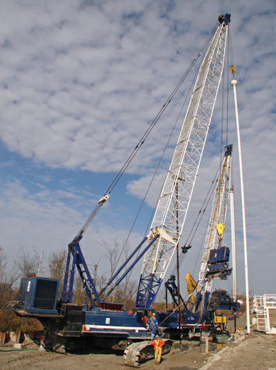
| The lattice boom crawler cranes on this project had the necessary capacity to handle the caissons (1.524 m diameter, open-ended steel tubes up to 27 m long), the vibratory hammer used to drive the caissons and the long concrete tremie pipe.
|
The road stabilization was part of an Ontario urban road widening project in the City of Brampton and Town of Caledon where Mayfield Road is being widened from two to four lanes from Inder Heights Drive and Heart Lake Road. The stabilization work was part of the project’s Stage Two works, which included earth grading, peat excavation, construction of storm water management pond facilities, and installation of sheet piling, Concrete Cylinder Pipe (CCP) water mains, sanitary sewer and storm sewers. Deep Foundation Contractors is a subcontractor to Metric Construction for the Stage Two works. The project’s Stage Three is scheduled for completion by the end of June, 2010 and includes asphalt paving on Mayfield Road from west of Summer Valley Drive to east of Valley View Drive. Stage Three’s scope of work also lists earth grading, construction of a storm water management pond, installation of storm sewers, roadway construction and surface restorations.
 |
|
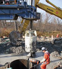
| A drill bucket was used to remove sloppy or wet material from within the caissons
|
Jose Montouto, project manager for the Region of Peel, describes how variable ground conditions were encountered on a 150 m swamp section of the new road and included peat layers as well as bands of saturated clay up to 23 m deep. Even in normal conditions, these materials would not be suitable subgrade for road construction, but it is particularly important here to have a stable road foundation as the scope of work includes the installation of three pressurized water mains of 750 mm, 600 mm and 300 mm diameter under the new roadway to service rapidly growing residential development. These water mains could easily be damaged by settlement and would cause serious problems if any failed.
Tony Medeiros, site supervisor for Deep Foundation Contractors, explains that peat and clay have been excavated and replaced using the caisson method. The caissons, 1.524 m diameter, open-ended steel tubes up to 27 m long, were driven into the ground and material excavated from within the caisson. Drier material near the surface was removed by an auger while a drill bucket was used to remove sloppy or wet material. As the bottom of the caisson was below the water table, the hole was kept flooded to prevent blowout from below. Low strength concrete containing only fine aggregate was then placed in the caisson utilizing a tremie pipe to place the concrete under water. This process was repeated until all the peat and clay in the road section had been replaced with low-strength concrete.
Construction of the north side wall followed with the creation of soldier piles every 3 m. To construct the soldier piles, caissons 18 m to 26 m long were driven and the low-strength concrete replaced with 20 MPa concrete. At the same time, a steel H beam was installed vertically into the centre of the 20 MPa concrete and kept in place with wedges. The concrete was topped off at the design elevation and the caisson then removed. Between the soldier piles, additional piles were installed utilizing 20 MPa concrete but without steel H beams to create a continuous structure known as a secant wall. The design of the south wall was generally similar, except that here soldier piles were installed every 3 m with no intermediate piles.
 |
|
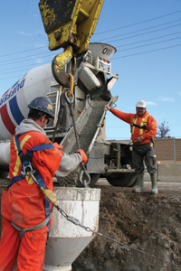
| Dufferin Concrete supplied some 20 m3 of concrete for each of the 184 caissons.
|
Once the soldier piles on the north side and south side have been installed, they will be connected by tie roads. In addition, the south side soldier piles will be supported by 27.5 m inclined long tie-back anchors underneath the existing roadway to anchor the whole foundation system. When the foundation work has been completed, the area will be surcharged with fill material to simulate traffic load and monitored for settlement. Water main construction will begin once it has been confirmed that the road foundation is stable and not susceptible to further settlement. There are 184 caissons in total, each requiring some 20 m3 of concrete, with concrete supplier Dufferin Concrete adding a four-hour retarder admixture in case of pouring delays on site.
In terms of mobile equipment, the large cranes used on these projects have the capacity to handle the long pile caissons and tremie pipe as well as the vibratory hammer used to drive the caissons. Here, the site equipment fleet included three lattice boom crawler cranes. The largest crane is a 136-tonne capacity lattice boom crane Link-Belt LS238 with a power pack that runs the vibratory hammer, while a 100-tonne capacity Link-Belt LS308 lattice boom crawler crane carries a Haines drill attachment and a second LS 308 is kept on standby.
The current model of the 238, the 238 HYLAB5, has a rated capacity of 136.08 tonnes. Attachment options include a 15.24 m to 79.25 m conventional boom; a 9.14 m to 22.86 m fixed jib new design, which can be installed as a fixed jib on a conventional boom or as a fixed jib on the luffing jib; a 24.38 m to 45.72 m luffing jib and 25.91 m to 50.29 m luffing boom. The crane’s counterweight removal system sets counterweights all the way to the ground while a new counterweight design utilizes a slab base with six wing weights to provide up to 41,730 kg of upper counterweight. The unit’s new boom design includes bar-type pendants and the boom connecting pins store on each extension for ease of transport. Ready for transportation, the main unit weighs 31,781 kg. The 238 H5 has a remote mounted oil cooler and is powered by a 284 hp Tier III compliant Isuzu AH-6HK1X engine.
 |
|
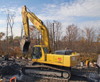
| Duties for this Komatsu PC450LC included the loading of excavated material and site cleanup
|
The 99.9-tonne-capacity lattice boom crawler crane currently available from Link-Belt is the 218HSL. Manufacturer’s literature states that the 218HSL can be transported in a total of four loads, the largest of which weighs 45,341 kg and includes the complete crane with base section, drums with rope and self-assembly device, less counterweights. Pile driving standard features include a spotter circuit, pile lead adapter mounting as well as controls, plumbing and mounting for optional third and fourth drums.
Attachment options include 12.2 m to 70.1 m of tube boom; 60.96 m boom plus 22.86 m jib combination for 64 m of maximum tip height. A 42.7 m plus 42.7 m maximum luffing attachment is also now available. The crane’s maximum line pull is 20,214 kg, while its track gauge is 4.32 m extended and 2.74 m retracted. The 218HSL has an operating weight of 87,423 kg and is powered by a 284 hp Tier III compliant Isuzu AH-6HK1X engine.
Print this page